αSTEP AR Series
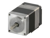
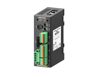
ARM24SA0K+ARD-KD2

| Product Classification | Product Name | CIF: List Price | FOB: List Price | Shipping Date |
|---|---|---|---|---|
| Motor | ARM24SA0K | MYR 537 | MYR 474 | 17 Working Days |
| Control Circuit | ARD-KD2 | Not available for purchase | ||
Included
- Motor: None
- Control Circuit: Connector for Power Input Terminal, Sensor Signal Connector, Input Signal Connector, Output Signal Connector
Specifications
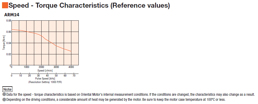
Characteristics
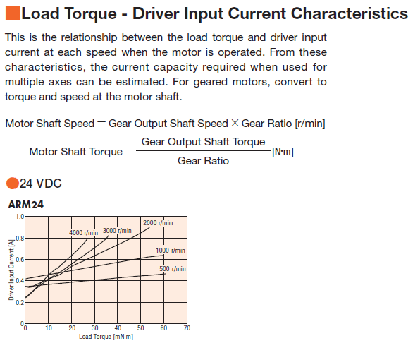
Load Torque - Driver Input Current Characteristics
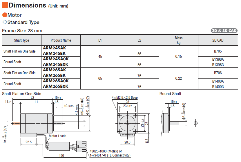
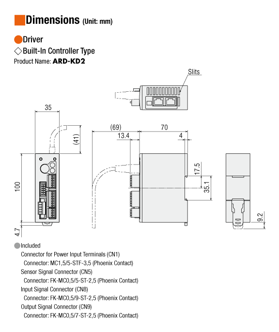
Dimensions
Data Download
Other Specifications
Motor General Specifications
| Item | Specifications | |
|---|---|---|
| Operating Environment (when operating) |
Ambient Temperature | −10∼+50°C (Non-freezing)*1: Standard type,TH·PS·PN Geared Types 0∼+40°C (Non-freezing)*1: Harmonic geared type |
| Ambient Humidity | 85% max. (Non-condensing) | |
| Atmosphere | No corrosive gases or dust. No exposure to water, oil or other liquids. | |
| Stop Position Accuracy |
ARM14, ARM15: ±5 arc minute (±0.083°) ARM24, ARM26, ARM46: ±4 arc minute (±0.067°) ARM66, ARM69, ARM98: ±3 arc minute (±0.05°) |
|
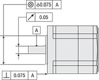
| Shaft Runout | 0.05 T.I.R. (mm) *2 | |
| Concentricity of Installation Pilot to the Shaft | 0.075 T.I.R. (mm) *2 | |
| Perpendicularity of mounting surface to the shaft | 0.075 T.I.R. (mm) *2 | |
- *1
- When a heat sink of a capacity at least equivalent to an aluminum plate with a size of 100×100 mm and 6 mm thickness
- *2
- T.I.R. (Total Indicator Reading): The total dial gauge reading when the measurement section is rotated 1 revolution centered on the reference axis center.
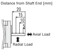
Permissible Radial Load and Permissible Axial Load
| Type | Motor Frame Size |
Product Name | Gear Ratio | Permissible Radial Load | Permissible Axial Load | ||||
|---|---|---|---|---|---|---|---|---|---|
| Distance From Shaft End [mm] | |||||||||
| 0 | 5 | 10 | 15 | 20 | |||||
| Standard Type | 20 mm | ARM14, ARM15 | − | 12 | 15 | - | - | - | 3 |
| 28 mm | ARM24, ARM26 | 25 | 34 | 52 | - | - | 5 | ||
| 42 mm | ARLM46, ARM46 | 35 | 44 | 58 | 85 | - | 15 | ||
| 60 mm | ARLM66, ARM66, ARLM69, ARM69 |
90 | 100 | 130 | 180 | 270 | 30 | ||
| 85 mm | ARLM98, ARM98, ARLM911, ARM911 |
260 | 290 | 340 | 390 | 480 | 60 | ||
| TH Geared Type | 28 mm | ARM24 | 7.2, 10, 20, 30 | 15 | 17 | 20 | 23 | − | 10 |
| 42 mm | ARLM46, ARM46 | 3.6, 7.2, 10, 20, 30 |
10 | 14 | 20 | 30 | − | 15 | |
| 60 mm | ARLM66, ARM66 | 70 | 80 | 100 | 120 | 150 | 40 | ||
| 90 mm | ARLM98, ARM98 | 220 | 250 | 300 | 350 | 400 | 100 | ||
| PS Geared Type | 28 mm | ARM24 | 5, 7.2, 10 | 45 | 60 | 80 | 100 | − | 40 |
| 42 mm | ARLM46, ARM46 | 5 | 70 | 80 | 95 | 120 | - | 100 | |
| 7.2 | 80 | 90 | 110 | 140 | - | ||||
| 10 | 85 | 100 | 120 | 150 | - | ||||
| 25 | 120 | 140 | 170 | 210 | - | ||||
| 36 | 130 | 160 | 190 | 240 | - | ||||
| 50 | 150 | 170 | 210 | 260 | - | ||||
| 60 mm | ARLM66, ARM66 | 5 | 170 | 200 | 230 | 270 | 320 | 200 | |
| 7.2 | 200 | 220 | 260 | 310 | 370 | ||||
| 10 | 220 | 250 | 290 | 350 | 410 | ||||
| 25 | 300 | 340 | 400 | 470 | 560 | ||||
| 36 | 340 | 380 | 450 | 530 | 630 | ||||
| 50 | 380 | 430 | 500 | 600 | 700 | ||||
| 90 mm | ARLM98, ARM98 | 5 | 380 | 420 | 470 | 540 | 630 | 600 | |
| 7.2 | 430 | 470 | 530 | 610 | 710 | ||||
| 10 | 480 | 530 | 590 | 680 | 790 | ||||
| 25 | 650 | 720 | 810 | 920 | 1070 | ||||
| 36 | 730 | 810 | 910 | 1040 | 1210 | ||||
| 50 | 820 | 910 | 1020 | 1160 | 1350 | ||||
| PN Geared Type | 28 mm | ARM24 | 5, 7.2, 10 | 45 | 60 | 80 | 100 | − | 40 |
| 42 mm | ARLM46, ARM46 | 5 | 80 | 95 | 120 | 160 | − | 100 | |
| 7.2 | 90 | 110 | 130 | 180 | − | ||||
| 10 | 100 | 120 | 150 | 200 | − | ||||
| 60 mm | ARLM66, ARM66 | 5 | 240 | 260 | 280 | 300 | 330 | 200 | |
| 7.2 | 270 | 290 | 310 | 340 | 370 | ||||
| 10 | 300 | 320 | 350 | 380 | 410 | ||||
| 25 | 410 | 440 | 470 | 520 | 560 | ||||
| 36 | 360 | 410 | 480 | 570 | 640 | ||||
| 50 | 360 | 410 | 480 | 570 | 700 | ||||
| 90 mm | ARLM98, ARM98 | 5 | 370 | 390 | 410 | 430 | 460 | 600 | |
| 7.2 | 410 | 440 | 460 | 490 | 520 | ||||
| 10 | 460 | 490 | 520 | 550 | 580 | ||||
| 25 | 630 | 660 | 700 | 740 | 790 | ||||
| 36 | 710 | 750 | 790 | 840 | 900 | ||||
| 50 | 790 | 840 | 890 | 940 | 1000 | ||||
| Harmonic Geared Type | 30 mm | ARM24 | 50, 100 | 100 | 135 | 175 | 250 | − | 140 |
| 42 mm | ARLM46, ARM46 | 180 | 220 | 270 | 360 | 510 | 220 | ||
| 60 mm | ARLM66, ARM66 | 320 | 370 | 440 | 550 | 720 | 450 | ||
| 90 mm | ARLM98, ARM98 | 1090 | 1150 | 1230 | 1310 | 1410 | 1300 | ||
| FC Geared Type | 42 mm | ARM46 | 7.2, 10, 20, 30 | 180 | 200 | 220 | 250 | − | 100 |
| 60 mm | ARM66 | 270 | 290 | 310 | 330 | 350 | 200 | ||
- The product names are listed such that the product names are distinguishable.
- PS, PN Geared Type: the value satisfies a calculated lifetime of 20,000 hours when either the permissible radial load or the permissible axial load are applied.
Click here for information about gearhead lifetime
Note
- The output shaft on the back shaft side of the motor output shaft of the double shaft product is for slit plate installation. Do not apply load torque, radial load, and axial load.
Radial Load and Axial Load
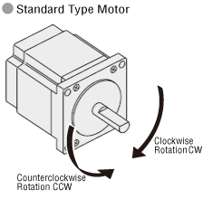
Rotation Direction
This indicates the rotation direction when viewed from the output shaft side.
The rotation direction of the gearhead output shaft relative to the standard type motor output shaft varies depending on the gear type and gear ratio. Please check the following table.
| Type | Gear Ratio | Rotation Direction as Viewed From the Motor Output Shaft Side |
|---|---|---|
| TS Geared Type | 3.6, 7.2, 10 | Same direction |
| 20, 30 | Opposite direction | |
| TH Geared Type Frame size 28 mm |
7.2, 10 | Opposite direction |
| 20, 30 | Same direction | |
| TH Geared Type Frame size 42 mm, 60 mm, 90 mm |
3.6, 7.2, 10 | Same direction |
| 20, 30 | Opposite direction | |
| SH Geared Type Frame size 28 mm |
7.2, 36 | Same direction |
| 9, 10, 18 | Opposite direction | |
| SH Geared Type Frame size 42 mm, 60 mm |
3.6, 7.2, 9, 10 | Same direction |
| 18, 36 | Opposite direction | |
| SH Geared Type Frame size 90 mm |
3.6, 7.2, 9, 10, 18 | Same direction |
| 36 | Opposite direction | |
| CS Geared Type | 5, 10, 15, 20 | Same direction |
|
FC Geared Type PS Geared Type PN Geared Type HPG Geared Type |
Overall gear ratio | Same direction |
| Harmonic Geared Type | 50, 100 | Opposite direction |
Driver Specifications
| Built-in Controller Type | Pulse input type | ||
|---|---|---|---|
| Maximum Input Pulse Frequency | − | Line driver output by host controller: 500 kHz (at 50 % duty) Open-Collector Output by host Controller: 250 kHz (at 50 % duty)*1 Negative Logic Pulse Input (Initial value) |
|
| Number of Positioning Data Sets | 64 Points | − | |
| Positioning Operation | Independent | ◯ | − |
| Linked | ◯ | − | |
| Linked 2 | ◯ | − | |
| Sequential | ◯ | − | |
| Direct | ◯ | − | |
| pushing | ◯ | ◯*2 | |
| Continuous Operation | ◯ | − | |
| JOG Operation | ◯ | − | |
| Return-To-Home Operation | ◯ | − | |
| Test Operation | ◯ | ◯*2 | |
| Control Module OPX-2A | ◯ | ◯ | |
| Data Setting Software MEXE02 | ◯ | ◯ | |
- *1
- The value when the general-purpose cable (CC36D1E) (sold separately) is used.
- *2
- Setting with extended function (OPX-2A or MEXE02)
Note
- Do not perform push-motion operation using geared types. Doing so may damage the motor or gearhead.
RS-485 Communication Specifications
| Protocol | Modbus RTU mode |
|---|---|
| Electrical Characteristics | EIA-485 Compliant, straight cable Use twisted-pair cables (TIA/EIA-568B CAT5e or better recommended), the max. total extension length is 50 m.* |
| Mode | Half duplex communication and asynchronous mode (data: 8 bits, stop bit: 1 bit or 2 bits, parity: none, even, or odd) |
| Transmission Rate | Selectable from 9,600 bps, 19,200 bps, 38,400 bps, 57,600 bps and 115,200 bps. |
| Connection Type | Up to 31 drivers can be connected to one host controller. |
- *If a specific wiring and layout causes the motor cable or power supply cable to generate a noise problem, shield the cable or use ferrite cores.
Driver General Specifications
| Item | Specifications | |
|---|---|---|
| Operating Environment (When operating) |
Ambient Temperature | 0 ∼ +50 ℃(Non-freezing) |
| Ambient Humidity | 85% max. (Non-condensing) | |
| Atmosphere | No corrosive gases or dust. No exposure to water, oil or other liquids. | |
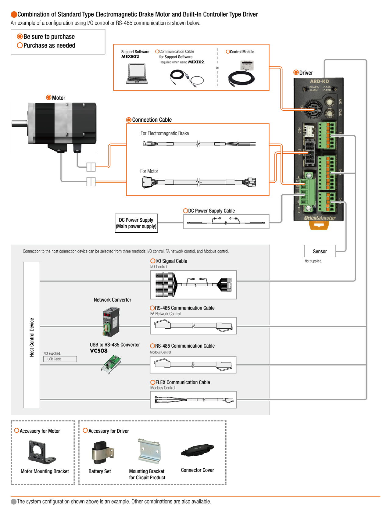
System Configuration
Related Products
Accessory - Network Converter
| Products | Features | ||
|---|---|---|---|
NETC02-CC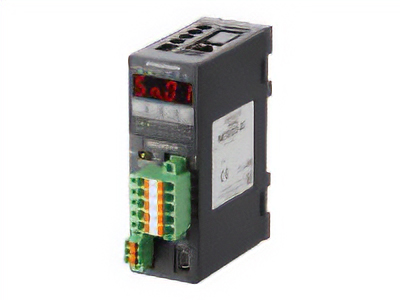
|
Features |
[CC-Link Ver. 2 Compatible] By supporting CC-Link Ver.2, you can simplify the ladder program and shorten the communication time for data sending and receiving. |
|
| Products |
NETC01-CC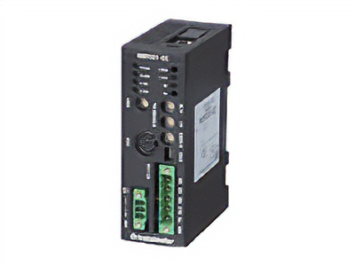
|
Features |
[CC-Link Ver.1.1 Compatible] By connecting a network converter, you can complete the wiring process with a single dedicated cable approved for the CC-Link communication protocol. |
| Products |
NETC01-M2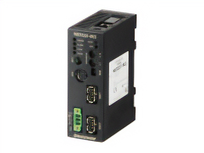
|
Features |
[MECHATROLINK-II Compatible] By connecting a network converter, the wiring process can be completed with a single dedicated cable approved for the MECHATROLINK-II communication protocol. |
| Products |
NETC01-M3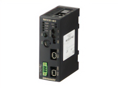
|
Features |
[MECHATROLINK-III Compatible] By connecting a network converter, the wiring process can be completed with a single dedicated cable approved for the MECHATROLINK-III communication protocol. |
| Products |
NETC01-ECT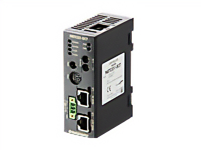
|
Features |
[EtherCAT Compatible] |
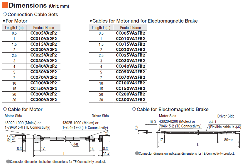
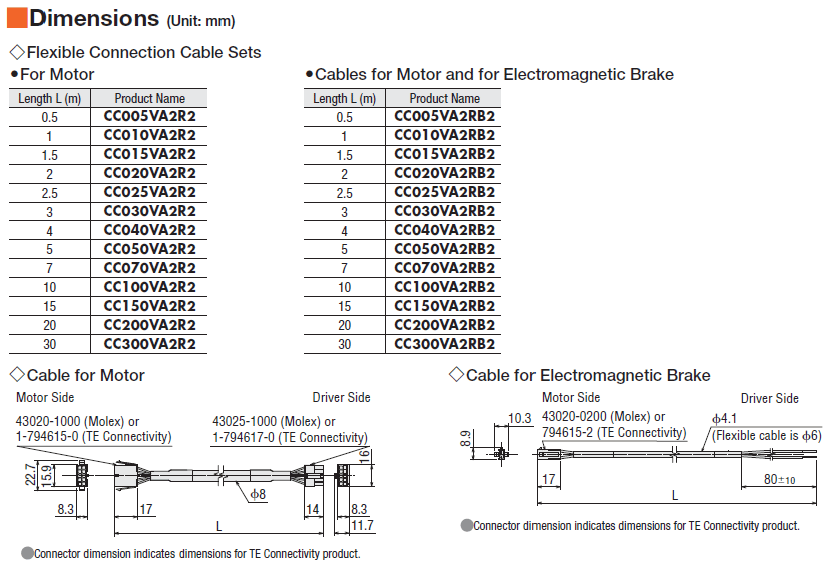
Cables and Accessories