2-Phase Stepper Motors PK Series
PK245M-03A
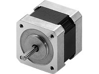
Motor
| Product Classification | Product Name | CIF: List Price | FOB: List Price | Shipping Date |
|---|---|---|---|---|
| Motor | PK245M-03A | MYR 311 | MYR 274 | 17 Working Days |
Specifications
Characteristics
Dimensions
Data Download
Other Specifications
General Specifications
| Specifications | Motor | |
|---|---|---|
| Thermal Class | 130 (B) [Standard Type With Terminal Box: UL/CSA Standards is approved at 105(A).] | |
| Insulation Resistance | The measured value is 100 MΩ min. when a 500 VDC megger is applied between the windings and the case under normal ambient temperature and humidity. | |
| Dielectric Strength | Under normal ambient temperature and humidity, no abnormalities were observed even if 1.0 kV at 50 Hz or 60 Hz is applied between the windings and the case of the motor for 1 minute. (0.5 kV for frame sizes of 42 mm max., and 1.5 kV for standard type with terminal box PK29□D) |
|
| Operating Environment (In operation) | Ambient Temperature | -10~+50 °C (non-freezing) |
| Ambient Humidity | 85 % max. (Non-Condensing) | |
| Atmosphere | No corrosive gases or dust Should not be exposed to water or oil. (Standard Type with Terminal Box: No corrosive gases. Should not be exposed to oil.) |
|
| Temperature Rise |
|
|
| Stop Position Accuracy*1 | ±3 arcmin (±0.05˚), PK26□J, PK26□JD: ±2 arcmin (±0.034˚) | |
| Shaft Runout | 0.05 T.I.R. (mm)*4 | |
| Radial Play*2 | 0.025 mm Max. (Load 5 N) | |
| Axial Play*3 | 0.075 mm max. (Load 10 N) [Load 1 N for PK21□, Load 2.5 N for PK22□] | |
| Concentricity of Installation Pilot to the Shaft | 0.075 T.I.R. (mm)*4 | |
| Perpendicularity of Mounting Surface to the Shaft | 0.075 T.I.R. (mm)*4 | |
- *1
- This value is for full step under no load. (The value changes with the size of the load.)
- *2
- Radial Play: Displacement in shaft position in the vertical direction when a 5 N load is applied perpendicular to the tip of the motor shaft.
- *3
- Axial Play: Displacement in shaft position in the axial direction when a 10 N (1 N for PK21□, 2.5 N for PK22□) load is applied to the motor shaft in the axial direction.
- *4
- T.I.R. (Total Indicator Reading): The total dial gauge reading when the measurement section is rotated 1 revolution centered on the reference axis center.
Note
- Disconnect the motor and driver when measuring insulation resistance, or conducting a dielectric strength test.
Permissible Radial Load and Permissible Axial Load
| Type | Motor Frame Size | Motor Product Name | Gear Ratio | Permissible Radial Load | Permissible Axial Load | ||||
|---|---|---|---|---|---|---|---|---|---|
| Distance From Shaft End [mm] | |||||||||
| 0 | 5 | 10 | 15 | 20 | |||||
| High-Torque Type | 28 mm | PK223, PK224, PK225, PK523, PK525 | - | 25 | 34 | 52 | - | - | Less than or equal to motor weight |
| 35 mm | PK233, PK235 | 20 | 25 | 34 | 52 | - | |||
| 42 mm | PK244, PK246, PK544, PK546 | 20 | 25 | 34 | 52 | - | |||
| 56.4 mm | PK264, PK266, PK268 | 61 | 73 | 90 | 110 | 160 | |||
| 60 mm | PK264, PK266, PK267, PK269 | 50 | 60 | 75 | 100 | 150 | |||
| High-Torque and High-Efficiency Type | 42 mm | PKE243, PKE244, PKE245 | 20 | 25 | 34 | 52 | - | ||
| High-Resolution Type High-Resolution Type With Electromagnetic Brake |
28 mm | PK523, PK524, PK525 | 25 | 34 | 52 | - | - | ||
| 42 mm | PK243, PK244, PK245, PK544, PK546 | 20 | 25 | 34 | 52 | - | |||
| 56.4 mm | PK264, PK266, PK268 | 54 | 67 | 89 | 130 | - | |||
| 60 mm | PK564, PK566, PK569 | 90 | 100 | 130 | 180 | 270 | |||
| Standard Type Standard Type Terminal Box Type Standard Type With Electromagnetic Brake |
42 mm | PK243, PK244, PK245, PK543, PK544, PK545 | 20 | 25 | 34 | 52 | - | ||
| 50 mm | PK256, PK258 | 54 | 67 | 89 | 130 | - | |||
| 56.4 mm | PK264, PK266, PK268 | 54 | 67 | 89 | 130 | - | |||
| 60 mm | PK564, PK566, PK569 | 63 | 75 | 95 | 130 | 190 | |||
| 85 mm | PK296, PK299, PK2913, PK596, PK599, PK5913 | 260 | 290 | 340 | 390 | 480 | |||
| SH Geared Type | 28 mm | PK223 | 7.2, 9, 10, 18, 36 | 15 | 17 | 20 | 23 | - | 10 |
| 42 mm | PK243 | 3.6, 7.2, 9, 10, 18, 36, 50, 100 | 10 | 15 | 20 | 30 | - | 15 | |
| 60 mm | PK264 | 3.6, 7.2, 9, 10 | 30 | 40 | 50 | 60 | 70 | 30 | |
| 18, 36, 50, 100 | 80 | 100 | 120 | 140 | 160 | ||||
| 90 mm | PK296 | 3.6, 7.2, 9, 10, 18, 36 | 220 | 250 | 300 | 350 | 400 | 100 | |
| TH Geared Type | 28 mm | PK523 | 7.2, 10, 20, 30 | 15 | 17 | 20 | 23 | - | 10 |
| 42 mm | PK543 | 3.6, 7.2, 10, 20, 30 | 10 | 14 | 20 | 30 | - | 15 | |
| 60 mm | PK564 | 70 | 80 | 100 | 120 | 150 | 40 | ||
| 90 mm | PK596 | 220 | 250 | 300 | 350 | 400 | 100 | ||
| PS Geared Type | 22 mm | PK513 | 4, 16 | 20 | 30 | - | - | - | 20 |
| 28 mm | PK523 | 5, 7.2, 10 | 45 | 60 | 80 | 100 | - | 20 | |
| 42 mm | PK545 | 5, 7.2, 10 | 73 | 84 | 100 | 123 | - | 50 | |
| PK543 | 25, 36, 50 | 109 | 127 | 150 | 184 | - | |||
| 60 mm | PK566 | 5 | 200 | 220 | 250 | 280 | 320 | 100 | |
| PK564 | 7.2, 10 | 250 | 270 | 300 | 340 | 390 | |||
| 25, 36, 50 | 330 | 360 | 400 | 450 | 520 | ||||
| 90 mm | PK599 | 5, 7.2, 10 | 480 | 540 | 600 | 680 | 790 | 300 | |
| PK596 | 25 | 850 | 940 | 1,050 | 1,190 | 1,380 | |||
| 36 | 930 | 1,030 | 1,150 | 1,310 | 1,520 | ||||
| 50 | 1,050 | 1,160 | 1,300 | 1,480 | 1,710 | ||||
| PN Geared Type | 28 mm | PK523 | 5, 7.2, 10 | 45 | 60 | 80 | 100 | - | 20 |
| 42 mm | PK544 | 5, 7.2, 10 | 100 | 120 | 150 | 190 | - | 100 | |
| 60 mm | PK566 | 5 | 200 | 220 | 250 | 280 | 320 | ||
| 7.2, 10 | 250 | 270 | 300 | 340 | 390 | ||||
| PK564 | 25, 36, 50 | 330 | 360 | 400 | 450 | 520 | |||
| 90 mm | PK599 | 5 | 480 | 520 | 550 | 580 | 620 | 300 | |
| 7.2, 10 | 480 | 540 | 600 | 680 | 790 | ||||
| PK596 | 25 | 850 | 940 | 1,050 | 1,110 | 1,190 | |||
| 36 | 930 | 1,030 | 1,150 | 1,220 | 1,300 | ||||
| 50 | 1,050 | 1,160 | 1,300 | 1,380 | 1,490 | ||||
| Harmonic Geared Type | 20 mm | PK513 | 50, 100 | 50 | 75 | - | - | - | 60 |
| 30 mm | PK523 | 110 | 135 | 175 | 250 | - | 140 | ||
| 42 mm | PK543 | 180 | 220 | 270 | 360 | 510 | 220 | ||
| 60 mm | PK564 | 320 | 370 | 440 | 550 | 720 | 450 | ||
| 90 mm | PK596 | 1,090 | 1,150 | 1,230 | 1,310 | 1,410 | 1,300 | ||
Inner Wiring Diagram of Motor
-
Unipolar (6 lead wires)
-
Bipolar (4 lead wires)
Standard Type with Terminal Box
PK26□AT
PK26□DAT, PK26□D1T
- A number indicating the length of the motor case is placed in □ in the product name.
PK29□EAT
PK29□DT
- A number indicating the length of the motor case is placed in □ in the product name.
Standards
Hazardous Substances
The product does not contain any substances (10 substances) exceeding the regulation values of the RoHS Directive (2011/65/EU, 2015/863/EU).
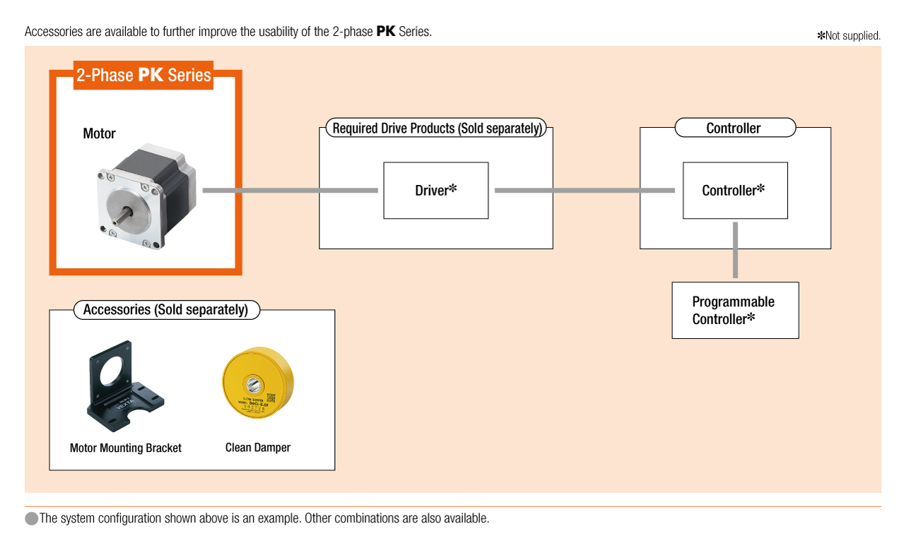
System Configuration
Cables and Accessories
close
close
close