What should I check if the AC Motor does not rotate?


-
Vex, I think you have a customer on the phone.
-
Yes, customer who has purchased single-phase induction motors is telling me that the motors don't work.
They wired it according to the wiring connection diagram without the load installed. They just bought it, so I don't think it's a malfunction, but what else should I check? -
You was able to recognize your customer's situation very well.
In that case, you can use a circuit tester to check the following three points to determine the cause.① Applied voltage and capacitor terminal voltage
② Conduction of the extension cable
③ Motor winding resistance -
The connection diagram for a single-phase induction motor looks like the one below, right? What should I check on the circuit tester?
Single-phase induction motor connection diagram -
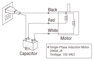
Let's start by examining ① the applied voltage and the capacitor terminal voltage.
Circuit tester A in the figure below can be used to check if voltage is being applied to the motor. To measure, select the "Mode to Measure AC Voltage: V~" on the circuit tester. If it's connected correctly, circuit tester A will be at 100 VAC equivalent to the power supply voltage.① Applied voltage and voltage between capacitor terminals -
I see. Next is the voltage between the capacitor terminals of circuit tester B, correct?
-
Before that, do you remember the role of a capacitor?
-
Um, I think I was taught...
-
Oh, I taught you properly. The role of the capacitor is to
(1) Determine the rotation direction
(2) Obtain the starting torque of the motor, increase the torque during rotationThese two.
-
Sorry...I'll review it properly.
-
Just make sure to remember those! You can check whether the capacitor is connected by measuring the voltage between the terminals of the capacitor. If it's connected correctly, circuit tester B will give you about 1.7 times the power supply voltage, without a load attached.
-
Now I see.
-
Another way to check if the capacitor is connected is to turn the shaft of the motor by hand. If the capacitor isn't connected, it'll start rotating in the direction of the applied force.
-
You don't need a circuit tester to check this. I'll remember that!
-
Next, check the ② conduction of the extension cable.
This is to check whether the wire that is connected to the motor and the power supply is broken or not. Turn off the power supply when you check. -
Just ask them to unplug it from the outlet.
-
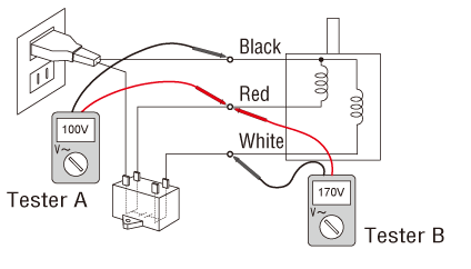
That’s right. Then, select the "Mode to Measure Conduction: ♪" on the circuit tester to measure as shown below.
② Extension cable conduction -
I understand.
-
There is a video of measurement method how to measure the voltage between capacitors, so please help who are measuring for the first time. In the video, I explain the procedure while actually measuring the voltage across the capacitor with a circuit tester.
Finally, check the ③ motor winding resistance.
By measuring the winding resistance, we can determine if the windings inside the motor are normal or not. -
This is to check if the motor is broken, right?
-
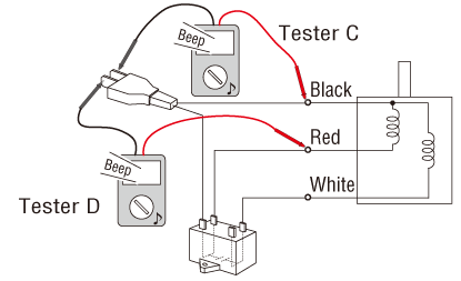
When measuring the winding resistance, remove the capacitor and cables and leave the motor alone. Select the "Mode to Measure Resistance Value: Ω" on the circuit tester to measure as shown in the figure below.
③ Winding resistance -
Thank you very much. Well, I'll go to check with the customer right away!
-
Wait a minute, Vex. Did you know that there's troubleshooting on the website?
-
Hmmm... I don't know. I'm sorry.
-
Not only tell what to do if it doesn't turn like this time, but it also tells what to do if you notice abnormalities in rotation direction, heat or sound.
-
That's right! When responding to customers, I will also provide troubleshooting information along with what you taught us!
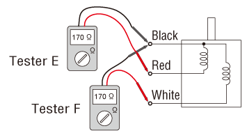
- February 15, 2021 Updated with the latest information.