Brushless Motors BLH Series
BLHM5100KC-10
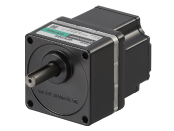
Motor


This product is currently no longer available for sale
| Product Classification | Product Name | CIF: List Price | FOB: List Price | Shipping Date |
|---|---|---|---|---|
| Motor | BLHM5100KC-10 | MYR 1,549 | MYR 1,366 | Discontinued Product (31.3.2026 discontinued) |
Included
- Motor: None
Gearhead: Mounting Screws, Parallel Key
Specifications
Dimensions
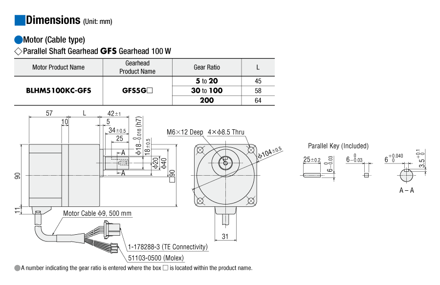
Motor/Gearhead
Data Download
Other Specifications
General Specifications
| Item | Motor | Driver | |
|---|---|---|---|
| Insulation Resistance | 100 MΩ or more when a 500 VDC megger is applied between the windings and the case after continuous operation under normal ambient temperature and humidity. |
After continuous operation at normal ambient temperature and humidity, the value measured with a 500 VDC megger between the power supply input and the heat sink is min. 100 MΩ. |
|
| Dielectric Strength | No abnormality is observed even with an application of 1.5 kVAC at 50 Hz between the coils and the case for 1 minute after continuous operation at normal ambient temperature and humidity. |
After continuous operation at normal ambient temperature and humidity, the value measured with a 500 VDC megger between the power supply input and the heat sink is min. 100 MΩ. (Except for RS-485 communication type) |
|
| Temperature Rise | After continuous operation at normal ambient temperature and humidity, the measured value using the thermocouple method is 50 °Cmax. for the temperature rise of the coils and 40°C*1 max. for the temperature rise on the case surface. |
After continuous operation at normal ambient temperature and humidity, the measurement value of the temperature rise of the heat sink is 50 °C max. using the thermocouple method. |
|
| Operating Environment | Ambient Temperature | 0∼+50°C (Non-freezing) | |
| Ambient Humidity | 85 % max. (Non-condensing) | ||
| Altitude | Up to 1000 m above sea level | ||
| Atmosphere | No corrosive gases or dust Should not be exposed to water or oil. Cannot be used in a radioactive area, magnetic field, vacuum, or other special environments. |
||
| Vibration | Must not be subjected to continuous vibration or excessive shock. Conforms to JIS C 60068-2-6, "Sine-wave vibration test method." Frequency Range: 10~55 Hz, Half Amplitude: 0.15 mm Sweep direction: 3 directions (X, Y, Z) Number of sweeps: 20 |
||
| Storage Condition*2 | Ambient Temperature | -25~+70°C (Non-freezing) Electromagnetic Brake Motor: -20~+70°C (Non-freezing) |
-25~+70°C (Non-freezing) |
| Ambient Humidity | 85 % max. (Non-condensing) | ||
| Altitude | Up to 3000 m above sea level | ||
| Atmosphere | No corrosive gases or dust Should not be exposed to water or oil. Cannot be used in a radioactive area, magnetic field, vacuum, or other special environments. |
||
| Thermal Class | UL/CSA Standards: 105 (A), EN Standards: 120 (E) | − | |
| Degree of Protection | Connector Type/Lead Wire Type IP40 Cable Type, Electromagnetic Brake Motor: IP65 excluding the connector section and the round shaft type mounting surface) |
IP00 | |
- *1
- Attach round shaft types to a heat sink (Material: aluminum) of one of the following sizes to maintain a motor case surface temperature of 90 °C max. (Except BLHM015.)
Heat Sink Size
| Product Name | Size (mm) | Thickness (mm) |
|---|---|---|
| BLM015, BLM030, BLM230, BLHM230 | 115x115 | 5 |
| BLM250, BLM 450, BLHM450 | 135x135 | |
| BLHM5100 | 200x200 |
- *2
- The value for storage condition applies to short periods such as the period during transport.
Note
- Do not measure insulation resistance or perform a dielectric strength test the motor and driver are connected.
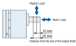
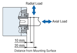
Permissible Radial Load and Permissible Axial Load
Parallel Shaft Gearhead
| Output | Gear Ratio | Permissible Radial Load |
Permissible Axial Load N |
|
|---|---|---|---|---|
|
10 mm From Shaft End N |
20 mm From Shaft End N |
|||
| 15 W | 5, 10, 15, 20 30, 50, 100 |
50 | − | 30 |
| 30 W | 5 | 100 | 150 | 40 |
| 10, 15, 20 | 150 | 200 | ||
| 30, 50, 100, 200 | 200 | 300 | ||
| 50 W | 5 | 200 | 250 | 100 |
| 10, 15, 20 | 300 | 350 | ||
| 30, 50, 100, 200 | 450 | 550 | ||
| 100 W | 5 | 300 | 400 | 150 |
| 10, 15, 20 | 400 | 500 | ||
| 30, 50, 100, 200 | 500 | 650 | ||
CS Geared Motor
| Output | Gear Ratio | Permissible Radial Load |
Permissible Axial Load N |
|
|---|---|---|---|---|
|
10 mm From the End of the Output Shaft N |
20 mm From the End of the Output Shaft N |
|||
| □42mm-15 W □42mm-30 W |
5 | 50 | - | 40 |
| 10, 15, 20 | 80 | - | ||
| □60mm-30 W □60mm-50 W |
5 | 150 | 190 | 70 |
| 10, 15, 20 | 200 | 260 | ||
Hollow Shaft Flat Gearhead
| Output | Gear Ratio | Permissible Radial Load |
Permissible Axial Load N |
|
|---|---|---|---|---|
|
10 mm From the Gearhead Mounting Surface N |
20 mm From the Gearhead Mounting Surface N |
|||
| 30 W | 5, 10 | 450 | 370 | 200 |
| 15, 20, 30, 50, 100, 200 | 500 | 400 | ||
| 50 W | 5, 10 | 800 | 660 | 400 |
| 15, 20, 30, 50, 100, 200 | 1200 | 1000 | ||
| 100 W | 5, 10 | 900 | 770 | 500 |
| 15, 20 | 1300 | 1110 | ||
| 30, 50, 100, 200 | 1500 | 1280 | ||
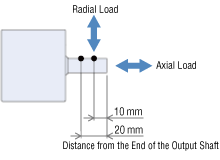
Round Shaft Type
| Output | Permissible Radial Load | Permissible Axial Load N |
|
|---|---|---|---|
|
10 mm From Shaft End N |
20 mm From Shaft End N |
||
| □42mm-15 W □42mm-30 W |
50 | − | 5 |
| □60mm-30 W □60mm-50 W |
70 | 100 | 15 (10) * |
| □80 mm-50 W | 120 | 140 | 20 |
| □90 mm-100 W | 160 | 170 | 25 |
- *The values in parentheses ( ) are for electromagnetic brake motor.
Cables and Accessories
close
close